Context
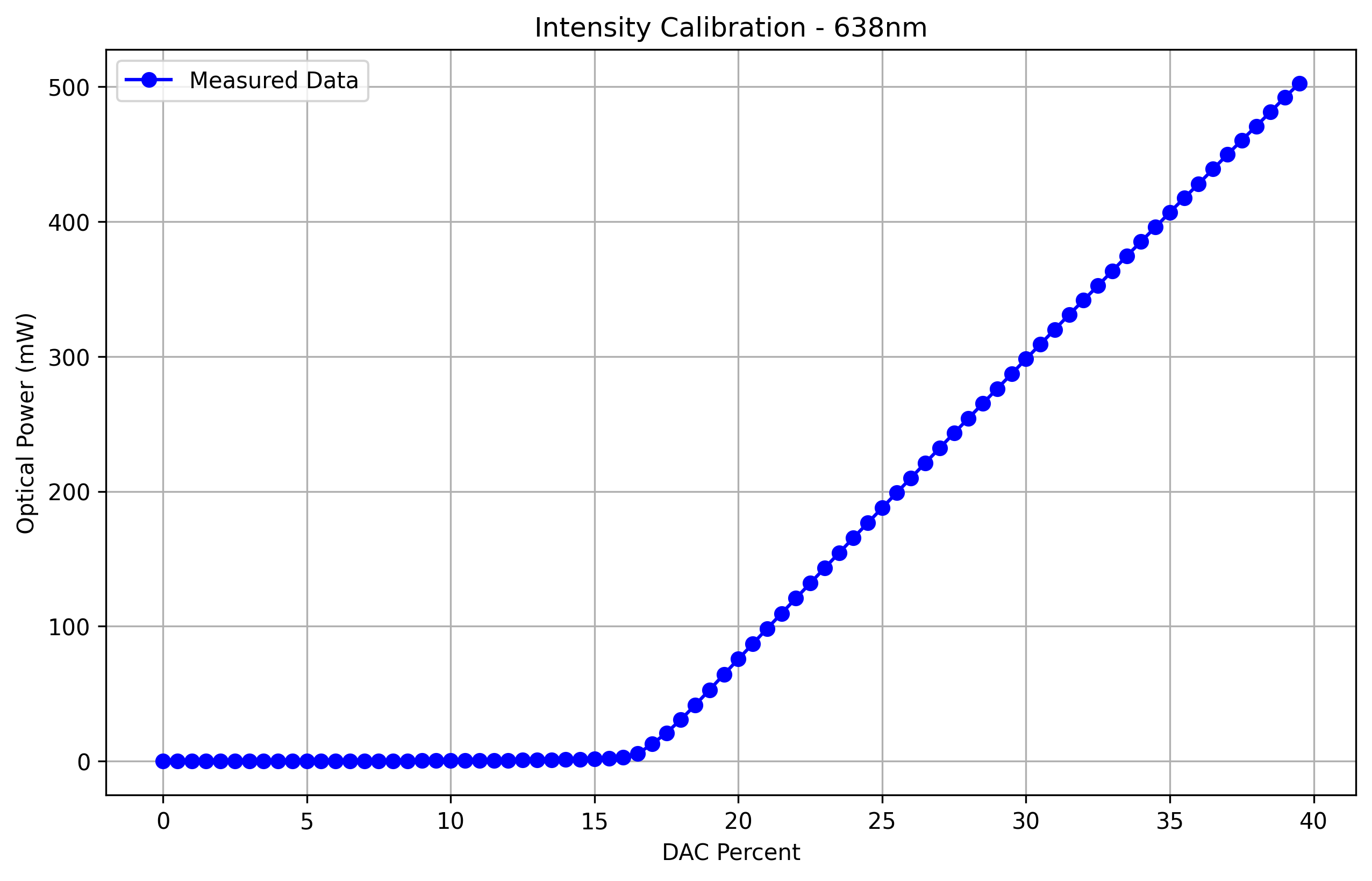
Currently “illumination intensity” in the software controls the DAC output, which control LED/laser current. For laser the output power vs laser current is nonlinear.
Prerequisites
- Thorlabs PM16 USB power meter (instructions for software here)
- 3D printed holder to mount the USB power meter at the sample plane
Changes
- Epi excitation wavelength to MCU illumination code mapping is now stored as
software/channel_mappings.json. A template is stored insoftware/configurations/channel_mappings.json. The wavelength here should match the channel named stored in channel configurations xml insoftware/acquisition_configurations. -
generate_intensity_calibrations.py is added for generating illumination intensity calibration, which will be saved to
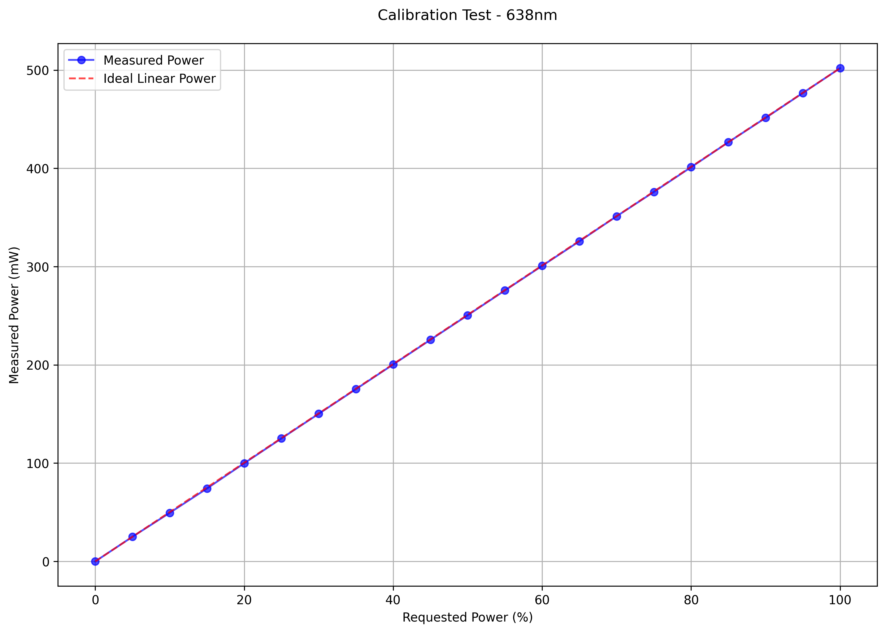
software/intensity_calibrations. Note that line 90 (WAVELENGTHS = [405, 470, 638]) needs to be edited, and the wavelength should match those in channel_mappings.json (and in channel configurations.xml). - test_intensity_calibration.py can be used to verify the calibration (output will be measured power vs illumination intensity).
- When calibration for a channel exists, the software will use the calibration to linearize the output.
Software to-dos
- IlluminationSource (MCU channel code) as a field should now be removed from channel configurations xml.