Setting it up
Step 1: run the following to note the changes you have made to the code and get the latest code
git diff
git stash
git pull
Step 2: edit and upload the latest firmware
-
in
octopi-research/firmware/octopi_firmware_v2/main_controller_teensy41/main_controller_teensy41.ino
(github link to this file), comment#include "def_octopi.h"and uncomment#include "def_octopi_80120.h" -
disconnect power and upload the firmware
For controllers shipped before Dec 2022, make sure to disconnect the power before uploading the firmware. Otherwise the board and the connected motorized stage can be permanently damaged.
Step 3: Check the hardware
- make sure the focus camera has its QR code facing downward
- make sure the laser diode is connected to the laser diode driver
connection must be made when power is off, otherwise the laser diode will be damaged
Step 4: add SUPPORT_LASER_AUTOFOCUS = True in the configuration txt file
Step 5: Adjust laser intensity and set the exposure time for the focus camera
- 5.1: Load a wellplate with cells in aqueous solution
- 5.2: Open the software
- 5.3: Bring the cells into focus with the main camera. Then turn off Live for the main camera.
-
5.4: Select the “Laser-based Focus” tab next to the “Live View” tab, set the exposure time to 2 ms and analog gain to 0, and click the “Live button” - you should see two spots on the live display. The two spots are from reflections at the media-glass interface and the glass-air interface.
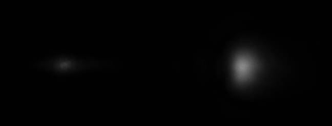
- If the spot on the left is saturated, turn the potentiometer counterclockwise to reduce the laser power
- If the spot on the left is dim, turn the potentiometer clockwise to increase the laser power
- If you don’t see any spot, do the following: (1) unpower the laser diode driver (2) disconnect the laser diode (3) connect the power (4) use a multimeter (in current mode) to measure the laser diode driver output current - use the potentiometer to set the current to 80 mA (make sure the value is below 100 mA) (5) disconnect the power (6) connect the laser diode.
Make sure the laser diode driver is disconnected from power when connecting/disconnecting the laser diode. Otherwise the laser diode will be permanently damaged.
-
5.5: You may also adjust the exposure time to make the left spot bright but without saturation. If you used an exposure time that is different from 2 ms, add
FOCUS_CAMERA_EXPOSURE_TIME_MS = xin the configuration txt file (x is the exposure time you’re using). - 5.6: If the two spots are at an angle, adjust the orientation of the focus camera to make the two spots roughly horizontal.
Using reflection-based autofocus in the GUI
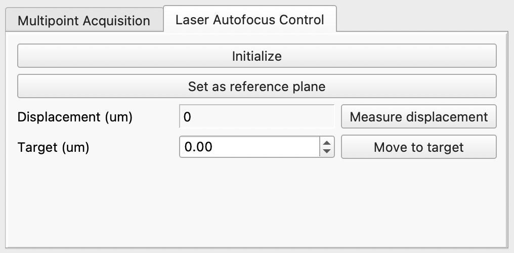
- Initialize: This will locate the spots, set the crop area (to increase speed), and calculate the pixel shift to displacement conversion (it will make one measurement, move the focus by 6 um, and make another measurement). Click this button when the cells are roughly in focus.
- Set as reference plane: this will set the current position as the reference plane, or the zero point for subsequent displacement measurement.
- Measure displacement: click this button will update the displacement measurement.
- Move to target: Click this button will move the objective to target displacement. The new displacement will be measured and displayed after the measurement. When moving in open-loop mode, you may want to click the button for a second time to reduce the effect of backlash.
Using reflection-based autofocus in multipoint acquisition
If you check the Reflection AF checkbox, the reflection-based focus controller will be re-initialized at the first FOV of the acquisition, set the current plane as the reference plane and move to this plane in all subsequent FOVs. If you also check the Contrast AF checkbox, a contrast-based autofocus will be performed in the first FOV and the resulting plane will be set as the reference plane.
Explanation of settings
-
HAS_TWO_INTERFACES: if set toTrue, the controller will look for two peaks. If set to false, the controller will directly find the centroid of the threshold image. Set toFalseif (1) using oil immersion objectives, (2) using a highly reflective surface (Si wafer, mirrors, metal coated slides), (3) using a high NA objective (e.g. 20x/0.75) and a thick slide (e.g. 1 mm). -
USE_GLASS_TOP: if set toTrue, the dimmer spot will be used for displacement measurement. The assumption is that an air objective is used and the top of the coverslip is in aqueous solution.
Below are other default settings that can be overwritten in the configuration txt file:
MAIN_CAMERA_MODEL = 'MER2-1220-32U3M'
FOCUS_CAMEARA_MODEL = 'MER2-630-60U3M'
FOCUS_CAMERA_EXPOSURE_TIME_MS = 2
FOCUS_CAMERA_ANALOG_GAIN = 0
LASER_AF_AVERAGING_N = 5
LASER_AF_DISPLAY_SPOT_IMAGE = True
LASER_AF_CROP_WIDTH = 1536
LASER_AF_CROP_HEIGHT = 256
SHOW_LEGACY_DISPLACEMENT_MEASUREMENT_WINDOWS = False
MULTIPOINT_REFLECTION_AUTOFOCUS_ENABLE_BY_DEFAULT = False