Assembly note for the excitation path (LED-based)
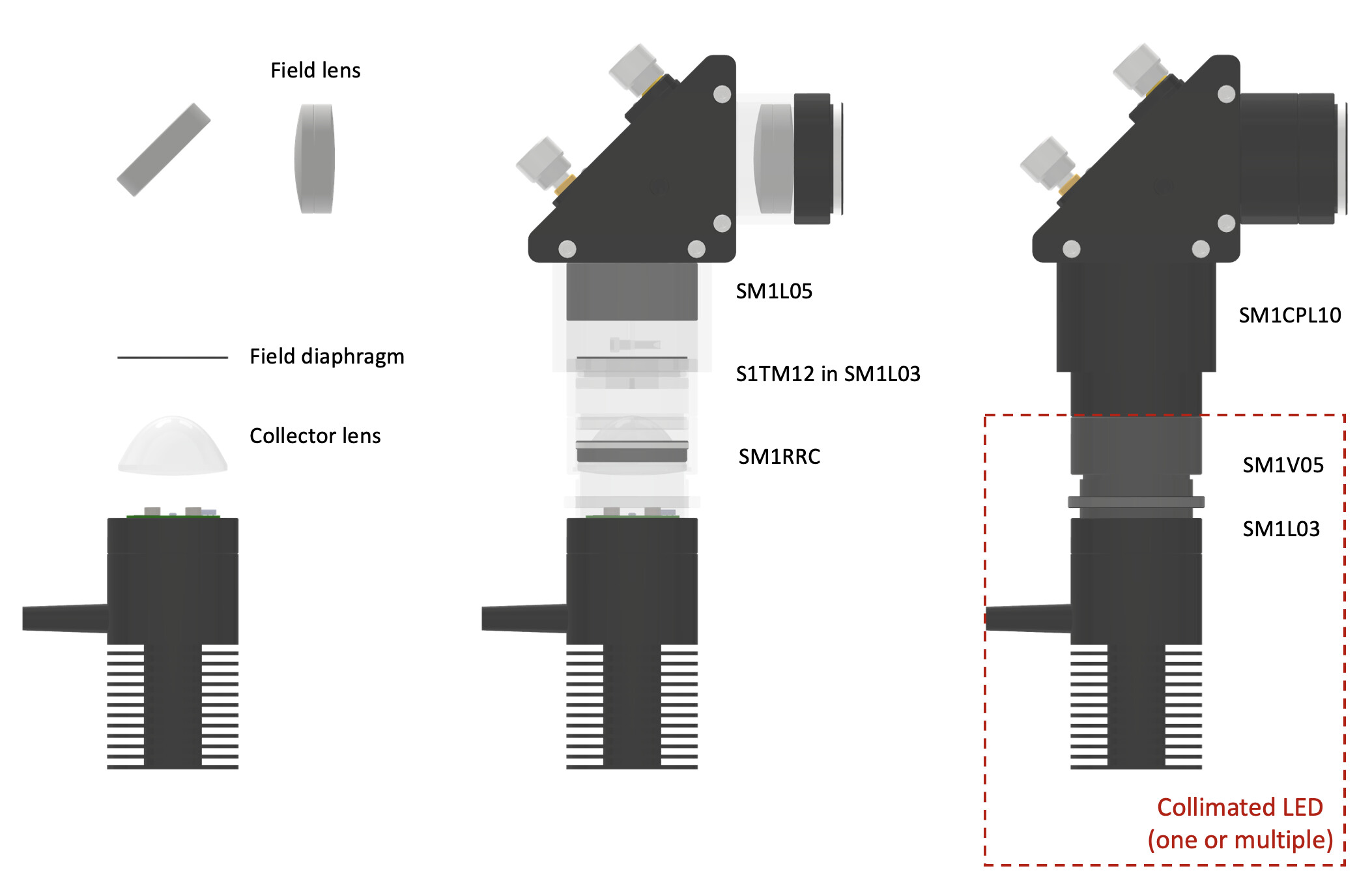
The diagram for the epifluorescence excitation is shown above.
First assemble the collimated LED (Thorlabs mounted LED + SM1L03 + SM1V05 + condenser lens + SM1RRC).
- Mount the condenser in SM1V05 with SM1RRC (make sure the orientation of the lens is correct)
- Connect the mounted LED, SM1L03 and SM1V05
- Point the assembly at a wall far way, turn on the LED, rotate SM1V05 until you see the image of the LED die on the wall, lock the position with the locking ring. Now the LED is roughly collimated.
Collimated LEDs of different colors can be combined with dichroic beam splitters mounted in CM1-DCH (pay attention to the mounting orientation - see below)
In the assembly you can have a field diaphragm to limit the illumination region to a defined area. For now you can glue a machined or laser cut square aperture to S1TM12. This piece is mounted in SM1L03, which is connected to the collimated LED assembly. The assembly is connected to the optical train using a clamping connector SM1CP10, so that the position and angle of the aperture can be adjusted.
When mounting the field lens, pay attention to its orientation.
Once the excitation path is fully assembled, it can be connected to the rest of the optical train. To obtain the best illumination performance (Köhler illumination), you need to image the LED to the back focal plane of the objective (for Olympus objective, the BFP is typically located inside the objective and 19.1 mm away from the flange). One adjustment procedure is listed below.
- Finish setting up the entire microscope.
- Load a sample and bring the sample into focus.
- Remove the sample.
- Remove the objective.
- Place a piece of paper at the location of the back focal plane of the objective (you can 3D print a spacer; in the future a spacer may be provided).
- Adjust SM1V05 so that the LED die is imaged to the paper (in focus on the paper).
- Lock SM1V05.
To adjust the field diaphragm, use a sample that is fluorescent over a large area, loosen SM1CP10 and carefully bring the assembly up or down till the boundary of the illuminated area becomes sharp.
Assembly note for the excitation path (laser-based)
Detailed instructions coming soon… (see preprint for details for now)
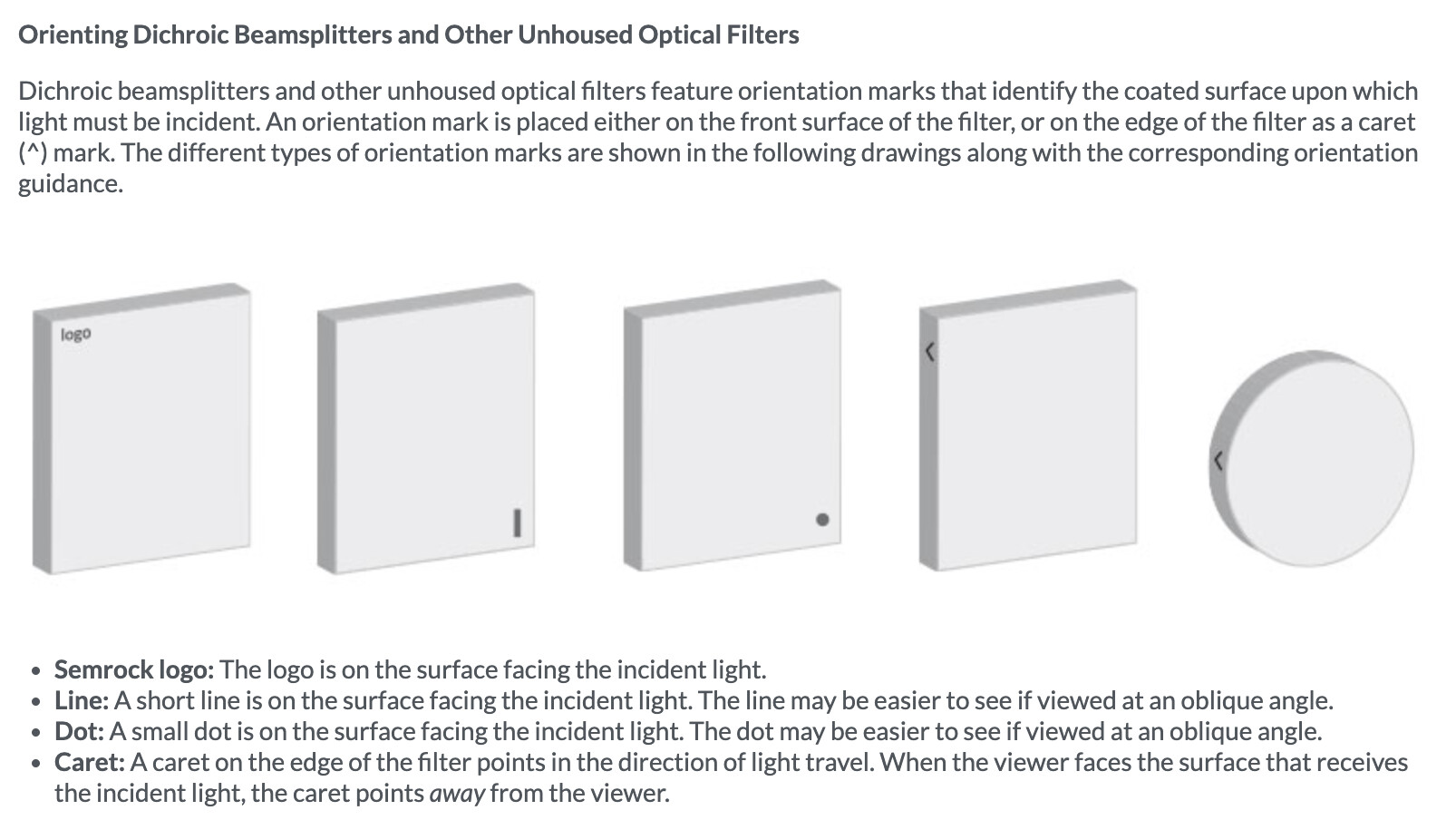
Orientation of filters and beamsplitters
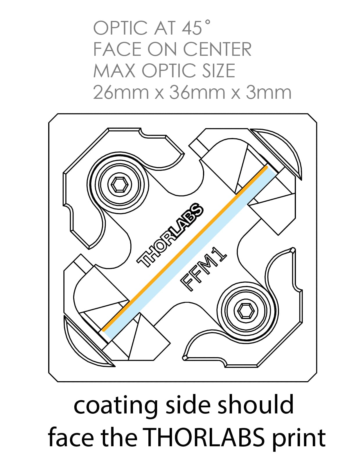
When mounting dichroic to Thorlabs CM1-DCH cube, make sure the coating side of the dichroic faces the THORLABS print:
Pay attention to the filter orientation when finishing the assembly:
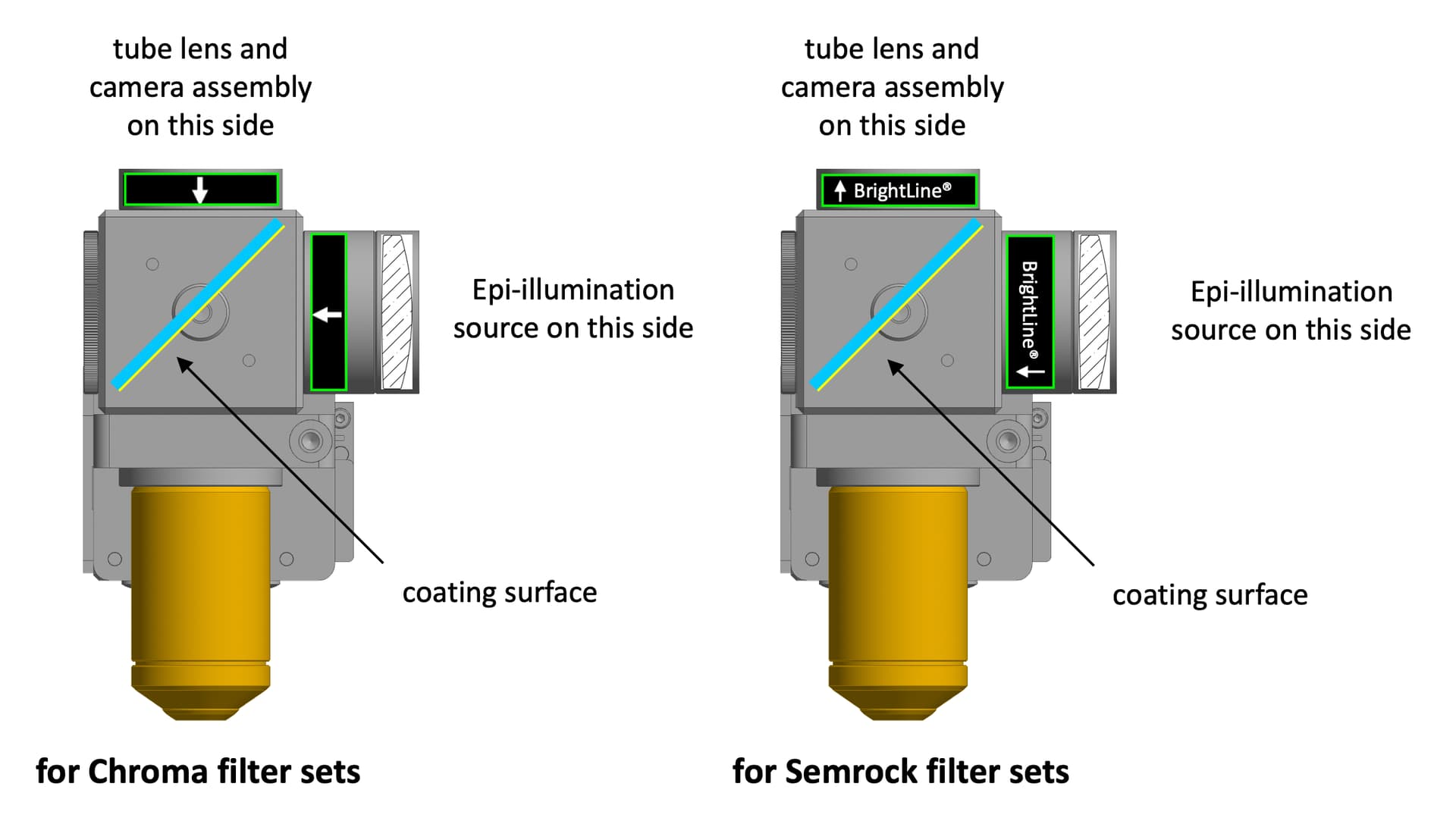
Chroma: Cleaning, Handling, and Orientation | Chroma Technology Corp.
- The dichroics either have an arrow on the side pointing to the coated side, or they are beveled on the coated side. The beveled side is the smaller surface.
Semrock: Semrock - The Standard in Optical Filters for Life Sciences (select What is Filter Orientation in the dropdown)