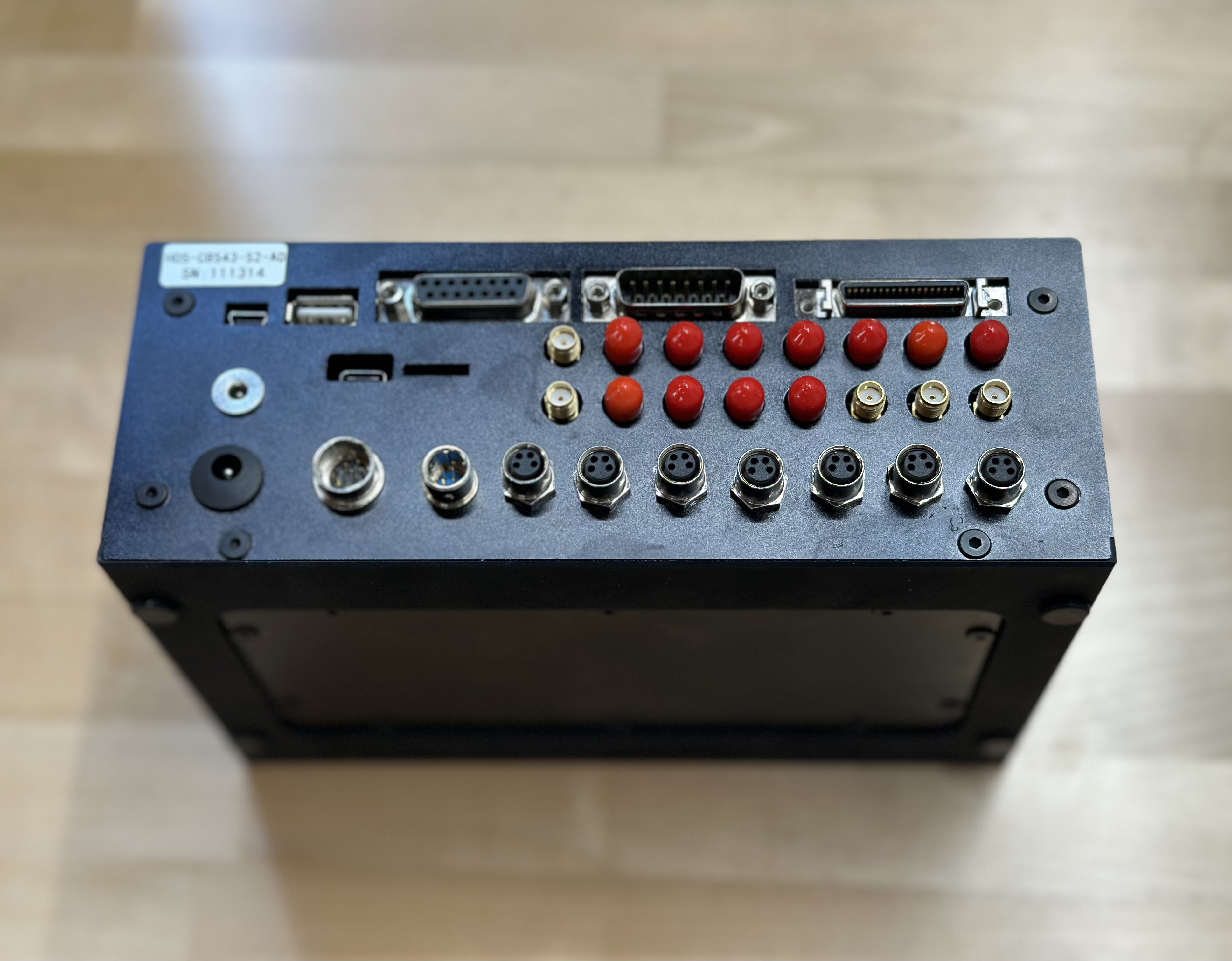
We have finally added our three epi-illumination fluorescence LED channels to the inverted SQUID hardware and connected them to the LED connectors of the controller. We haven’t been able to identify yet where and how to configure the channels, so that the correct (or any for that matter) light is turned on. Could you please point us in the right direction?
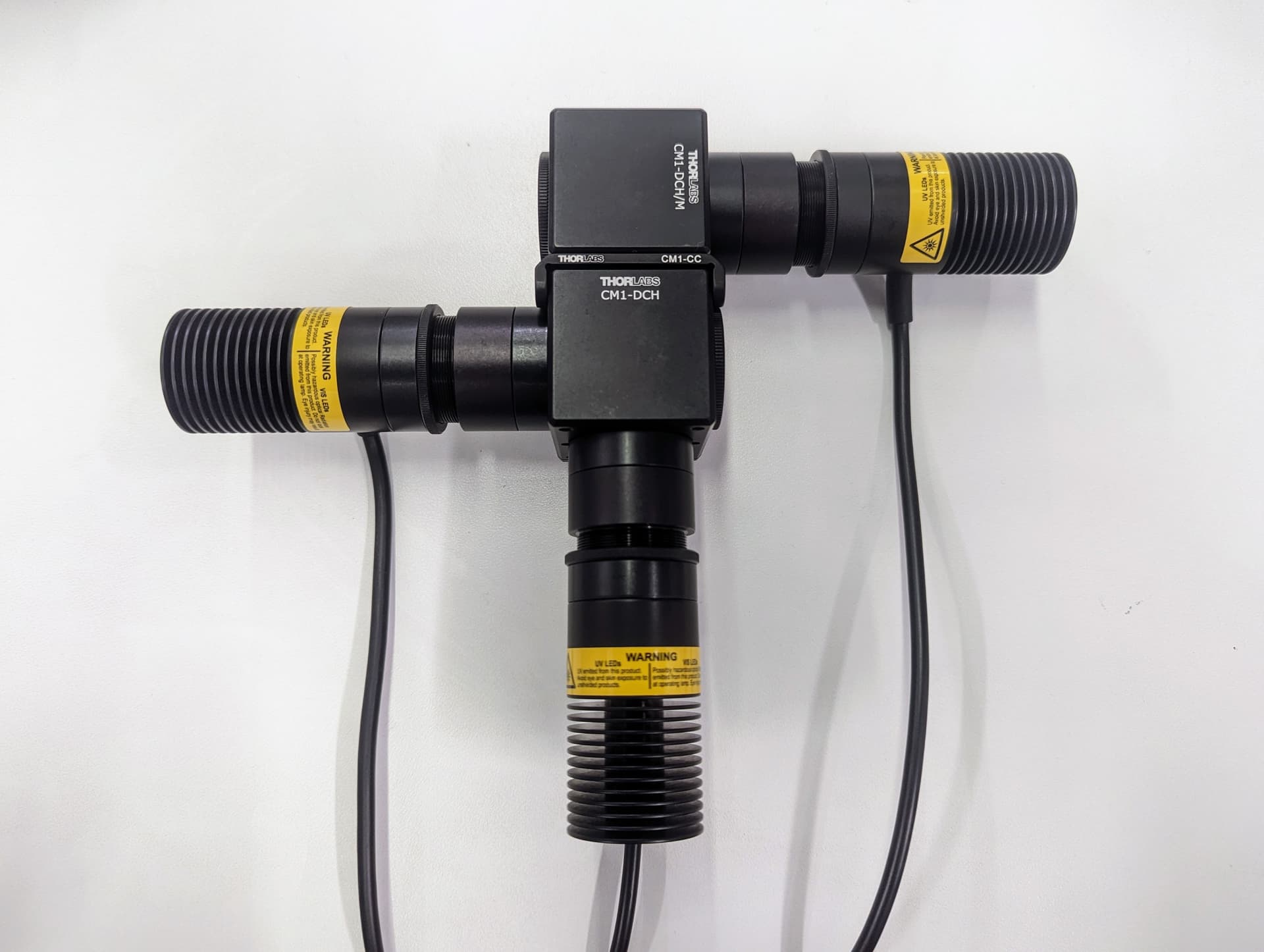
The first five 4-pin 8 mm LED connectors from left to right are mapped to “405”, “488”, “561”, “638” and “730”. You for you can update the channel name by editing the channel_configurations.xml file (e.g. by changing Fluorescence 405 nm Ex to Fluorescence 375 nm Ex.
1 Like
Thank you! That order assignment was an important information. We did see the xml before but the reason it didn’t work before was an error in the environment installation (a mix of mamba and pip installations). Now it’s all working and I just relabelled the 561 channel to 638 in order not to have to move the driver board inside the controller.
With the environment reinstallation, now also the LED matrix variations (right, left, etc) started working. Question: How do you generate the computational phase contrast images? Do you take the images separately and compute them with a script, or is there a SQUID-specific implementation?
Here’s the code from Waller lab: GitHub - Waller-Lab/DPC_withAberrationCorrection: M. Chen, Z. F. Phillips, and L. Waller, Quantitative differential phase contrast (DPC) microscopy with computational aberration correction, Opt. Express 26(25), 32888-32899 (2018).. We’re working on some improvement and will keep you posted.
1 Like
Thanks for the replies. We got some excellent fluorescence images with the IMX226 camera and LED illumination (I know there are still a few alignment improvements to be made). ![]()

Caption: Test run of microfluidic droplets in oil, with encapsulated single-cells (that’s why many droplets are empty) of GFP expressing E.coli after overnight culture to form little colonies inside the droplets.
Is there more documentation available on the LED matrix channel use and settings? We haven’t tried the DPC code yet, but we also don’t fully understand the available options. E.g. when selecting the channel LED GREEN - all the LEDs are still on (not just the green LEDs) but it’s somewhat different to the FULL LED setting.
@MakerTobey are you referring to BF LED matrix full_G? That’s for the Sci microscopy LED dome only for now. These _G, _R, _B were created for synthesizing RGB images using monochrome cameras for a user with Sci microscope LED dome. We can quickly make these also work with our own LED matrix. Apologies for the lack of documentations.
Curious where the shading from the top left corner comes from.
About the shading: First I thought the LED array was not mounted in the center, but that was not the solution. It seems strangely that the objective and the camera was not perfectly aligned. I could fix it with the slightly off-center mounting of the filter wheel (see other post) and now it seems fine. I’m not sure how this could happen.